[Expert Views] Solutions in Patents: How to Prevent Thermal Runaway of Lithium Batteries from Cell, Module and BMS (Part 3)
As electric vehicles have become more and more popular, fire accidents occurred within EVs are occasionally reported in the news. If we take a closer look at photos taken during these fire accidents, such photos often reveal that damages to the EVs are more severe than that seen with conventional engine vehicles. Mostly, they are caused by the power source of the EVs – Lithium batteries. Lithium batteries contain highly flammable lithium metal and organic materials. When the battery catches fire, it keeps burning at high temperatures, thus making it difficult to be put out, or even causing an explosion. Such phenomenon is called thermal runaway. Since lithium batteries have be widely used in EVs, thermal runaway has become a critical problem for the industry to solve to improve driving safety. In previous articles, patent solutions from the aspect of cell manufacturing and module design have been discussed. In this article, related patents of battery management system (BMS) will be analyzed.
Battery Management System (BMS)
When battery modules are being used, thermal runaway occurs mainly for two reasons: one is that the battery is ruptured by collision; the other is that the battery is damaged due to improper use. In order to solve thermal runaway caused by rupture, solutions that improve cell materials or enhance module design have been developed. For cell material improvement, non-flammable materials such as solid-state electrolyte may be employed. Module enhancement includes the improvement of mechanical strength of modules and fire extinguishing mechanisms.
In order to avoid improper use, it is necessary to monitor the status of the batteries and manage the batteries to avoid issues such as over-charging or over-discharging. As mentioned in the previous article, Tesla’s MODEL S has a capacity of 85kWh, which includes 7,104 lithium battery cells
[1]. The voltage, temperature and capacity of each cell might be different, particularly after charging cycles. Through BMS, the condition of battery modules can be monitored to avoid thermal runaway in advance. Fig. 1 shows technologies able to prevent thermal runaway related to BMS, including state of charge (SOC) and state of health (SOH) monitoring, charging/discharging control, battery balancing or various abnormality detection. Detailed solutions are described below.
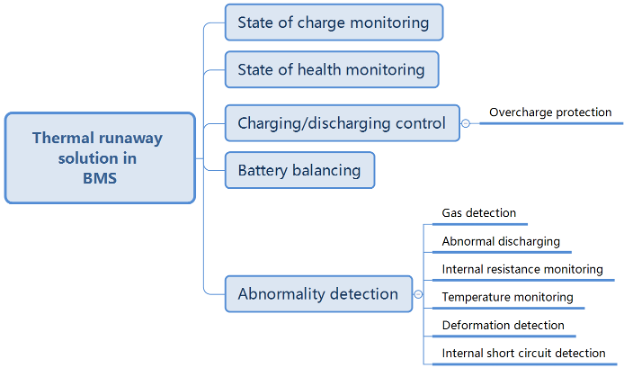
Fig. 1 Technologies of preventing thermal runaway in battery management system
State of Charge (SOC) Monitoring
State of charge (SOC) represents the percentage of a battery’s current capacity compared to its full capacity. Taking the example of a battery with a 3Ah full capacity, a 50% SOC means the current capacity is 1.5Ah. During both charging or discharging cycles, the battery’s SOC is controlled within a certain range, such as 90% to 10%, to avoid over-charging or over-discharging. When using the battery, it is necessary to monitor the SOC, particularly for EVs where it is important to estimate remaining mileage. There are correlations between cell voltage and current capacity, as shown in Fig.2. Therefore, by detecting cell voltage, it is feasible to estimate the battery’s current capacity. The correlation between cell voltage and current capacity differs based on cell materials. This correlation must be determined before using the battery. It can be affected by temperatures, charging or discharging currents and the battery’s cycle life. As shown in Fig.2, the curves of cell voltage and current capacity changes as the charging or discharging cycle increase. Consequently, when calculating battery capacity, it is necessary to calibrate the results for different cell temperatures and charging cycles to obtain a more accurate current capacity. Taking California Institute of Technology’s patent US10556510 as an example, the factors considered when calculating battery capacity include enthalpy change (ΔH). The calibrated curves remain substantially unchanged at different charging cycles to allow a convenient mapping of cell voltage (open-circuit potential) to capacity, as shown in Fig.3.
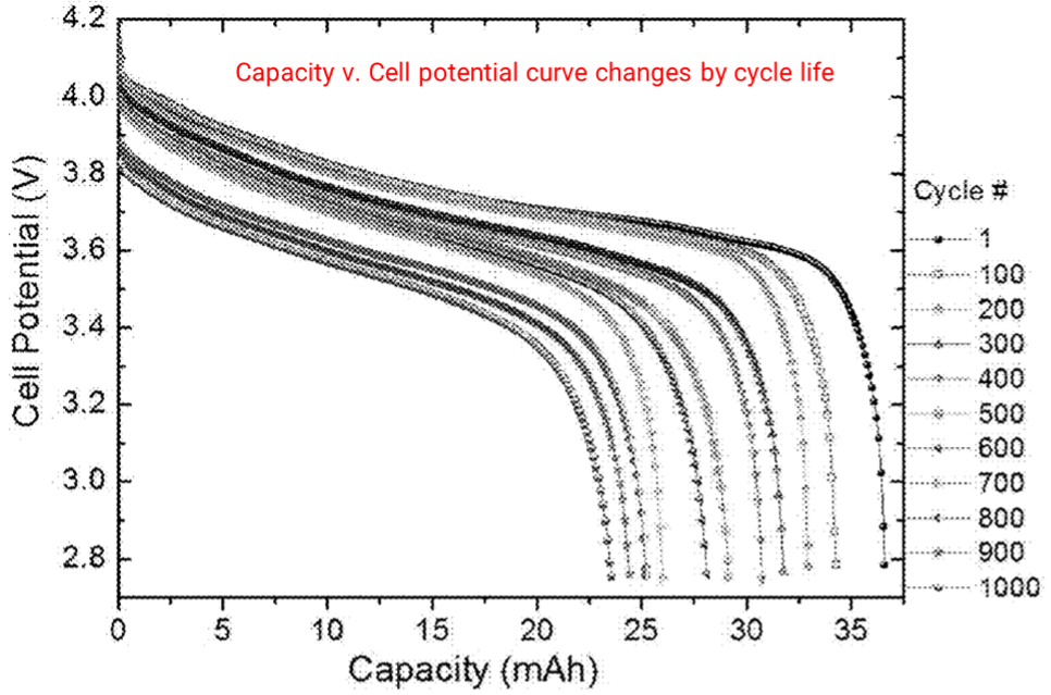
Fig.2 Drawing of California Institute of Technology’s patent US10556510
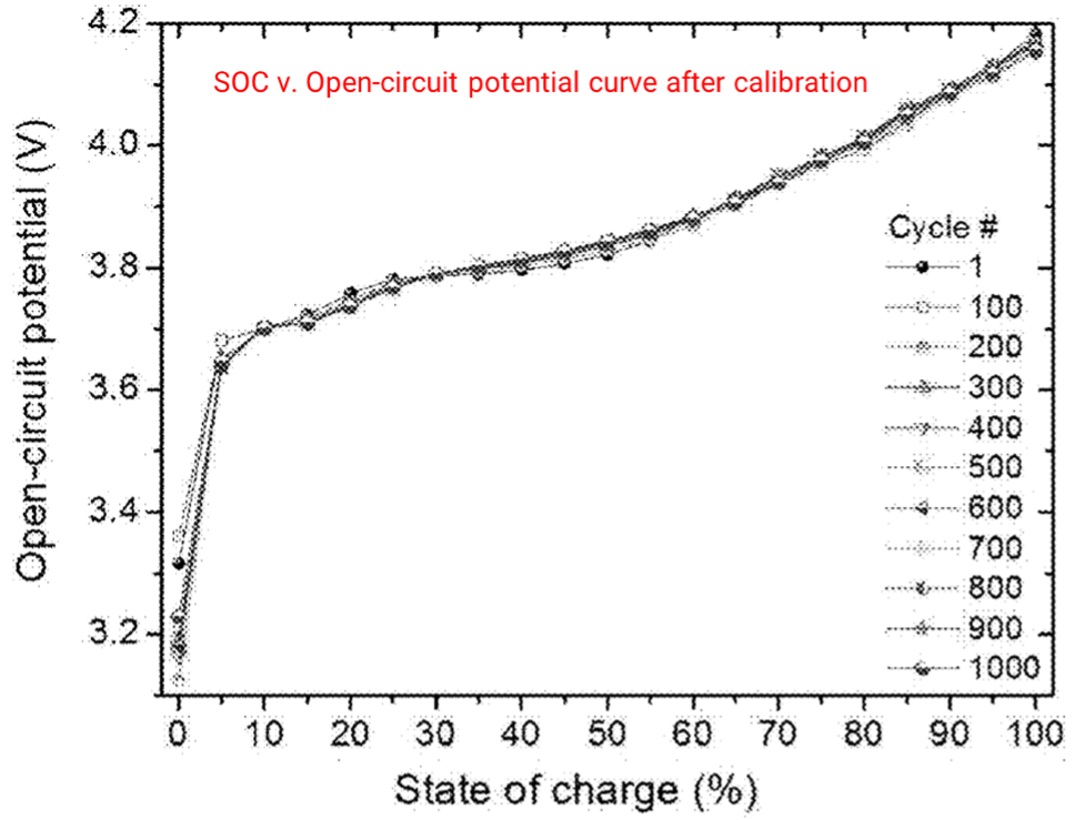
Fig.3 Drawing of California Institute of Technology’s patent US10556510
State of Health (SOH) Monitoring
With repetitive charging or discharging cycles, the battery ages with more capacity decay and higher internal resistance. State of health (SOH)
[2] represents the aging level or abnormality level of a battery compared to an ideal one, such as a new battery. In EVs, it is necessary to monitor the SOH of batteries to replace aged battery modules and avoid reduced travel mileage or even the risk of thermal runaway. Samsung’s patent US11402433 is a good example of a method to determine the health parameters of a battery. This method adds a low frequency current signal or voltage signal to the battery to obtain a responded low frequency charging current or charging voltage. The internal resistance can be calculated to estimate the battery’s SOH, as shown in Fig.4.
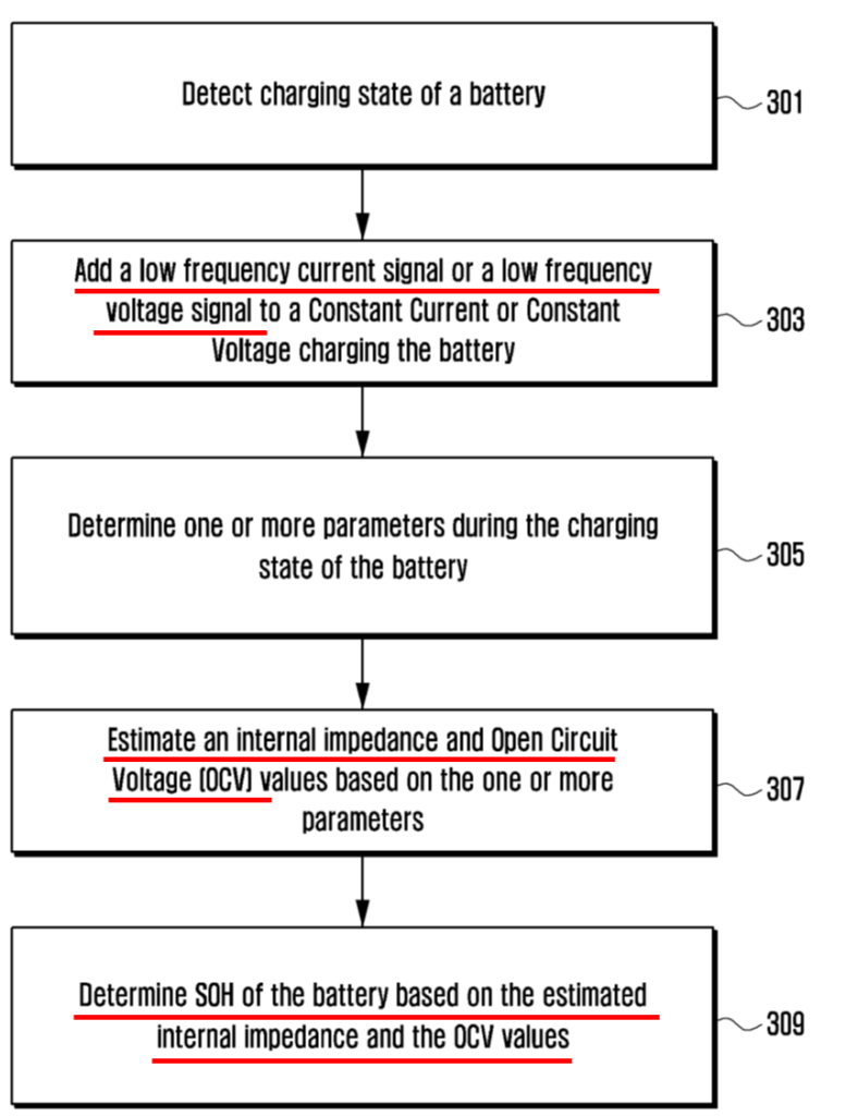
Fig.4 Drawing of Samsung’s patent US11402433
Charging/Discharging Control
When charging a battery, constant current or voltage is often used. High charging current or voltage can provide fast charging, but also increase the possibility of lithium metal deposition on the anode, therefore inducing thermal runaway, particularly when the battery is nearly full. It is then necessary to optimize the charging method to achieve fast charging and minimized metal deposition. Let us take Honda’s patent US11177675 as an example, as shown in Fig.5. The patent provides a charging method which detects the battery’s SOC. The charging current is determined by the SOC, i.e., when the SOC increases, the charging current decreases. Through this manner, the possibility of lithium deposition during the charging process can be reduced.
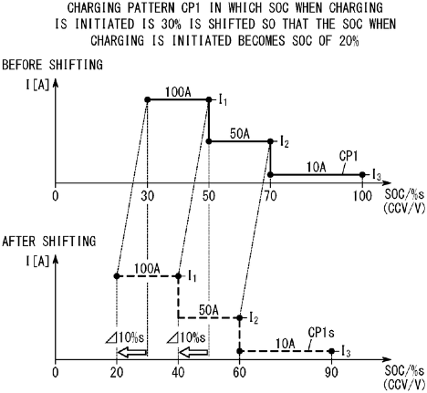
Fig.5 Drawing Honda’s patent US11177675
Battery Balancing
A battery pack system includes multiple battery modules. A battery module consists of multiple cells connected in series and parallel. Due to the different chemical properties of the cells and their using environments, the cells’ electrical properties after charging and discharging cycles are different. When these cells are connected to a module, some cells may be over-charged while some are undercharged during the charging process. Prolonged over-charge and over-discharge adversely affect the battery cells and accelerate the aging process. Therefore, it is necessary to balance the batteries to minimize their difference. Let us take ITRI’s patent US20210328441 as an example, as shown in Fig.6. The patent provides a method for controlling the cell balance procedure. Battery units are charged separately according to their voltage differences to achieve voltage balance.
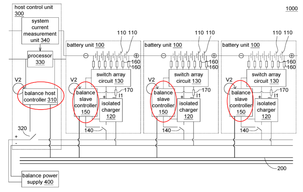
Fig.6 Drawing of ITRI’s patent US20210328441
Overcharge Protection
Overcharge protection is needed when charging batteries. Here, we may take Tesla’s patent US8659270 as an example, as shown in Fig.7. Besides conventional charging control, an additional overcharge protection device is employed. When the overcharge occurs and the conventional charging control fails, the overcharge protection device creates a short circuit to melt a fuse connected in the current path, thereby stopping the charging procedure.
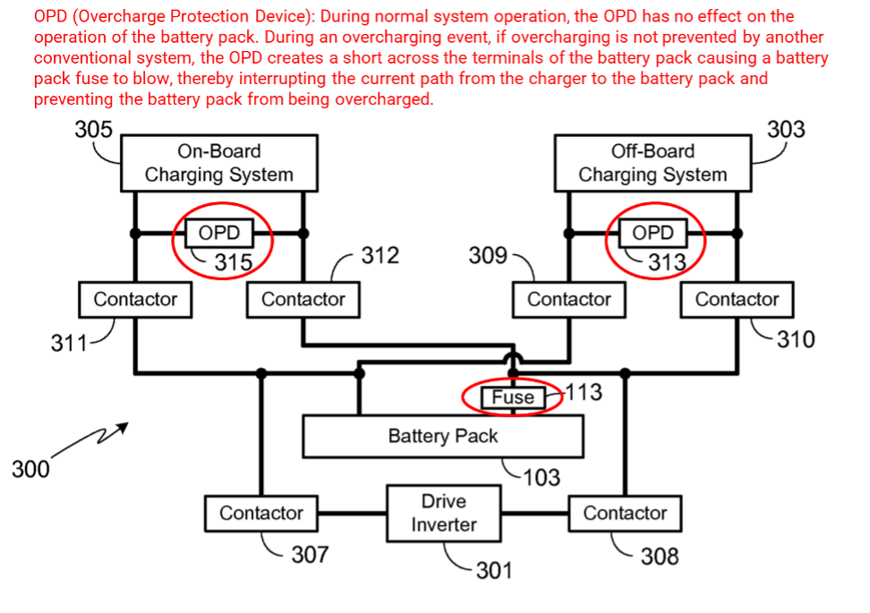
Fig.7 Drawing of Tesla’s patent US8659270
Abnormality Detection
Abnormality detection aims at detecting the various parameters of a battery and determine whether the battery is malfunctioning. This includes the detection of the items listed below:
Gas detection: As previously mentioned, when thermal runaway occurs, batteries internally generate harmful gases, which may be released outside through venting holes. Sensors are used to detect gases released from the batteries to detect thermal runaway.
Abnormal discharging, internal short circuit: When the dendrites are initially formed inside a battery, which causes an internal short circuit, the dendrites can be melted. Before the occurrence of a thermal runaway, the battery slowly self-discharges. When the dendrites accumulate to a certain amount, the positive and negative electrodes electrically connected are likely to cause severe thermal runaway. Therefore, by monitoring abnormal self-discharging, thermal runaway can be prevented in advance.
Internal resistance, temperature: An aged battery has increased internal resistance, which cause higher temperature rise during the charging/discharging process. By detecting internal resistance and temperature change, thermal runaway can be better predicted.
Deformation detection: When the pressure inside a battery rises due to generation of gases, the battery may expand and deform. Detecting the formation of the battery may also predict the occurrence of thermal runaway. Let us take Hyundai’s patent Hyundai US20220045371 as an example, as shown in Fig.8. A strain gauge is attached to a surface of a battery module to measure its deformation. When the deformation exceeds a predetermined level, the BMS sends warning signals calling for the replacement of the battery module.
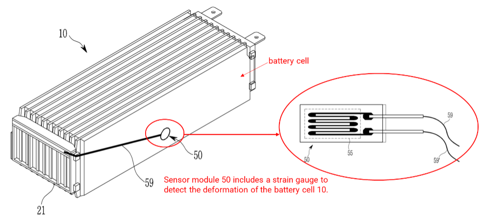
Fig.8 Drawing of Hyundai’s patent US20220045371
In summary, to increase the safety of EVs’ lithium batteries, the industry has proposed various solutions from cell improvement, battery modules and battery management system, as shown in Fig.9.
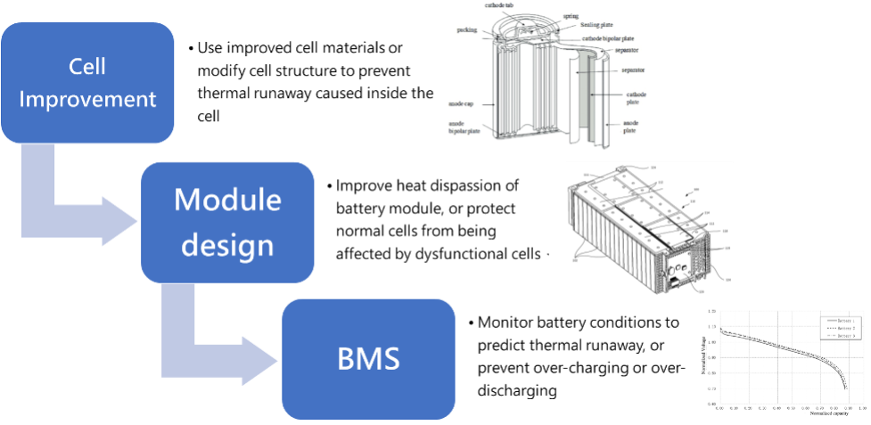
Fig.9 Technologies related to prevent battery thermal runaway
In this series of articles, the patent landscape of battery thermal runaway solutions was explained by introducing registered patents and major patent owners’ technologies. The author hopes that these articles might inspire inventors to come up with more innovations to continuously improve the safety of batteries, particularly in the field of electric vehicles.
[1] Tesla Model S - https://en.wikipedia.org/wiki/Tesla_Model_S
[2] State of Health- https://en.wikipedia.org/wiki/State_of_health

Author: Jean Chou
Taiwan Patent Attorney / Certified Valuation Analyst / Co-Chair of Business IP Management Committee, TWPAA / Vice President of
WISPRO Technology Consulting Corporation
Email: jeanchou@wispro.com

![[Expert Views] How Tesla Explores its Patent Assets](https://www.mih-ev.org/s3/mih%2Fwp-content%2Fuploads%2F2023%2F01%2FWispro-Expert-Views.png)