Enter the Supply Chain of EV in Five Steps: An analysis of International Automotive Reliability Specs
Honda sets to stop selling pure fuel vehicles in Europe in 2022. Volvo sets to become a brand of pure electric vehicle in 2030. Ford targets to stop selling fuel vehicles in Europe in 2030. While leading car manufacturers are flocking to shift to making EVs (electric vehicles) in the next ten years, demands for car chips bottomed out and skyrocketed in Q4 2020, leading to a severe shortage of semiconductors.
The large demands for automotive semiconductors come in two categories. One is power semiconductors required by the aforementioned electric vehicles which consume 7 ~ 10 as much as that of their conventional counterparts. The other is the sensor components found in electric vehicles (usually denoted by level 2, 3, 4 or 5). Leading global car brands, including M-Benz, BMW and TOYOTA, have launched series of AI- based driverless smart cars featuring automatic driving, automatic parking, collision warning and automatic braking to name a few.
Electronic components facilitating these functions are subject to a series of stringent reliability tests, designed to ensure their faultlessness and damage free operation, before they can be adopted to ensure the best protection of rider safety.
The automotive industry has been well known for being closed to outsiders. Leading car manufacturers do not focus on "cost down" in their production as the lives and health of riders are much more important. Poor product design and/or reliability may result in large sums in compensation lawsuits. This makes them reluctant to change suppliers. This is not the case with the rocketing demands for "AI electric vehicles" and "ADAS (Advanced Driver Assistance Systems)," as costs of automotive electronics now account for 40-50% of total car prices (up to 8,000 ICs per car). These two new factors are pressing car makers to source electronic product supply chains out of their traditional comfort zone. The more we rely on electronic system response, the more we mandate better functional safety and the least impact on personal safety imposed by risks of malfunctions. Aiming for better quality and reliability of electronic components, vehicle makers and tier 1 system providers are setting failure rate of the former to one part per billion (ppb) and promoting the concept of Zero Defect throughout the entire supply chain.
Featuring short product life cycles, the consumer electronics industry has been living with generation changes every 3-5 years. This mandates capacity and strength of "time to market," enabling scores of startups to debut into the mainstream rapidly. This is not so in the automotive industry. New technologies are seldom adopted by hot-selling models. Instead, the latter would most likely feature
the most mature and reliable goods. The author of this article suggests that startups fighting for survival aim at after markets (AM) or raise product reliability if they are targeting brand owners/Tier 1.
This article shall explore ways to improve product reliability in terms of requirement specifications and validation results/V curves (see figure 1) emphasized by both
SAE J1211 and
ISO 26262. The goal is to help those seeking to enter the AI automotive supply chain to learn about the essentials of car electronic component design and verification using my practical experience serving at iST.
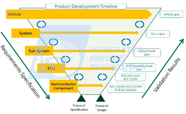
Figure 1: V-curve, car component design and verification process (source: SAE J1211)
5 Steps in Internationally Reliable Automotive Quality Grade Validation
To develop a product and function, the automotive manufacturer defines System function -> Sub system function -> Electronic control unit (ECU) to employ -> Semiconductor components to use from left to right and top-down, as shown in figure 1, while validating requirements compliance happens in reverse order. That is, assuring quality from the very beginning is the only way to make highly reliable products, as "unstable foundations lead to collapse." Without observing the V-curve there is no way to ascertain the causes of product failure: poor quality of the product at the previous level, a process issue, or poor design by you yourself?
- Step 1:Component level – active components AEC-Q100 compliant, discrete semiconductors AEC-Q101
compliant (2021 edition), LED AEC-Q102 compliant (2020 edition), MEMS AEC-Q103 compliant,
MCM (Multi-Chip Modules) AEC-Q104 compliant and passive components AEC-Q200 compliant
- Step 2:PCB level – printed circuit board (PCB) IPC-6012DA compliant
- Step 3:Board level – board level reliability (BLR) of solder joints after mounting on PCB
- Step 4:Board level – PCBA process quality verification and validation
- Step 5:System level – standard specification from system module to Tier 1 / brand owners
Step 1: Component Level– AEC-Q Series
Addressing reliability verification over automotive ICs, the top 3 American vehicle manufacturers, Chrysler, Ford and GM, established the Automotive Electronics Council (AEC) in 1994 to set up quality control standards for automotive components. As AEC standard compliant electronics could also be adopted by Chrysler, Ford and GM at the same time, components makers were encouraged to exchange product feature data. This, in turn, ramped up the implementation of common automotive components and facilitated the fast growth of vehicle components.
Leading automotive makers around the world are setting AEC-Q100 as the mandatory requirement of active components for safety relevant ECUs amid climbing interest in AEC-Q200. This author suggests domestic manufacturers take steps in dealing with the latter as it may become mandatory in the future. AEC-Q102, the LED AEC component specification in 2017, is now the bible of automotive LEDs.
Regarding AEC-Q compliant electronic components, AEC-Q004 (Zero Defects) is a strategic framework aiming to apply the industry’s best processes, methods and tools or the component supplier exclusive defect screening and inspection mechanism to process design, product design, production and product/manufacturing improvement to reduce defects.
Step 2: PCB Level– IPC-6012DA Compliant
PCBs bridge active and passive components. You may rework failed components but not replace any PCB after all its components are removed. A PCB is, in essence, the key electronic automotive component.
Automotive PCBs are most likely validated according to IPC-6012 rather than any exclusive validation method. The IPC-6012DA, the first automotive specific PCB validation and acceptance specification by IPC in 2016, is the first step by IPC to regulate PCB makers competing in this fast growing market. It includes Thermal shock endurance testing, High temperature endurance testing, Humidity storage testing, Conductive anodic filament testing (CAF testing), Surface insulation resistance testing (SIR testing) and so on. This standard is now an important reference for brand owners and Tier 1 in PCB reliability verification.
Step 3: Board Level – Automotive Component Solder Joint Reliability after Being Mounted (Board Level Reliability, BLR)
The Board Level Reliability (BLR) is the most common global method to verify IC component solder joint reliability after being mounted on PCB. It has been a routine test item for hand-held devices; however, as more IC components are used in cars which increase the complexity of the automotive electronic system, the BLR has gradually become one of the important test items of automotive electronics.
Tier 1 module makers are making rising efforts in creating proprietary board level tests, including Bosch, Continental, and TRW. The AEC also come up with AEC-Q104 qualification in 2018 to clearly define the test items of BLR even though it merely includes Temperature Cycling Test (TCT) and Drop Test. However, BLR tests mentioned in AEC-Q 104 are for multi-chip modules only. Other common packages are excluded from this scope, which is not completely in accordance with the specifications of Tier 1 makers; AEC-Q104 is treated as a big step in the BLR general standard. See following table for the testing conditions of Board level required by Tier 1 module makers. Considering the booming of automotive market this year, we may look forward to the update of AEC-Q104 by the Automotive Electronics Council (AEC).
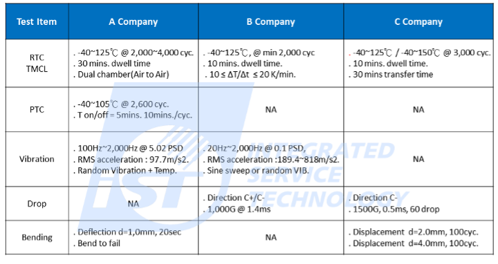
Table 1: The testing conditions of Board level required by Tier 1 module makers
1. The Top Five Solder Joint Failure Types Suffered by Board Level Automotive Chips Found in iST Labs:
(1) Solder joint size and layout (2) Solder joint alloy ingredients (3) PCB design mechanism and material selection (4) Reflow temperature and flux residual (5) Underfill material surrounding solder joint (see figure 2)
The aforementioned failures (2), (3), and (5) may be influenced by thermal expansion coefficients, which, in turn, may lead to different deformation levels as automotive chips are most likely operating in very high temperatures. In addition to the aforementioned vibration stress, the repetitive contraction and expansion due to changing temperatures may pull and press solder joints and break them. Selecting chip materials with closer thermal expansion coefficients can reduce temperature-related stress greatly. Most consumer goods like computers and cellphones enjoy warranty periods of around 2-5 years while the life cycles of automotive chips may last 10-20 years. This requires carefully designed test conditions and early adoption of these factors in initial chip development. Far more stringent safety and reliability requirements in the automotive industry over computer and mobile phone products not only extend the service life of chips but also improve remedy schedules and costs after failure analysis.
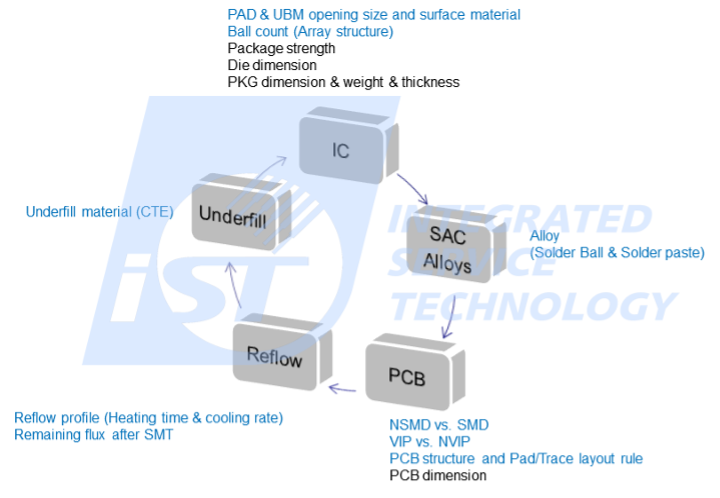
Figure 2: Top five solder joint failure types suffered by board level automotive chips
2. Do BLR Test Conditions of Consumer Electronics Remain Applicable to Automotive Electronics?
This is one of questions most frequently asked by our customers, and the answer is “No”. These conditions no longer apply as the operation environment and structure of car borne platform differs. Chips employed in-vehicle are constantly subject to vibration, mechanic stress and poor external conditions especially when cars are running. A product’s qualified consumer electronics requirements may fail early in practical operation environment.
Take the vibration test; handheld products are most likely subject to simulated ordinary land, sea, and air shipment conditions while the vehicle ones shall pay more attention to temperature and humidity durability and resistance against temperature and vibration due to long time exposure to external environment. Environment at Frigid Zone and Tropical Zone differs; temperature of confined space under direct sunlight may hit 100°C or even 150°C measured close to engine. To better mimic the real operation environment the factor of vibration is added in the test environment. That is, the combined vibration test known to us. Besides vibration and temperature test, the solder joints should subject to such as push, pull and cyclic bending test to ensure the strength of it is safe to the rider.
- Step 4: PCB Assembly Level– PCBA Process Quality Verification and Validation
The RoHS implemented by the EU in July 2006 requires that the Pb content in electronic products shall be less than 1000ppm. Replacing the tin-lead solder process for electronic products, in use for more than half a decade, with a Pb-free process mandates a whole new review and validation process for equipment, test methods, product quality and reliability, among others. The melting point of Pb-free material rose to 217℃ from the 183℃ melting point of tin-lead material, which, in turn, results in hardening, and brittle solder joints with poor fatigue resistance. Process yield becomes very hard to improve as a result of tin whiskers caused by solder joint flaws. This hampers its adoption in the medical, defense, and automotive industries when compared with its adoption in the consumer electronics industry due to the extremely high demands on reliability.
The AEC-Q100 Version G released in 2007 came without Pb-free validation requirements. It was addressed in the Q005 (PB-FREE TEST REQUIREMENTS) written by the AEC in 2009 and version H of AEC-Q100 in 2014 finally had Pb-free validation tests, including Solderability, Solder heat resistance, and Whisker. The automotive industry eventually marched into the era of environmental protection.
Thanks to lessons learned in implementing a Pb-free process for consumer electronics products, manufacturers are better equipped in managing the challenges of Pb-free and adapting it into the automotive phase. See figure 3 for a Pb-free validation flowchart.
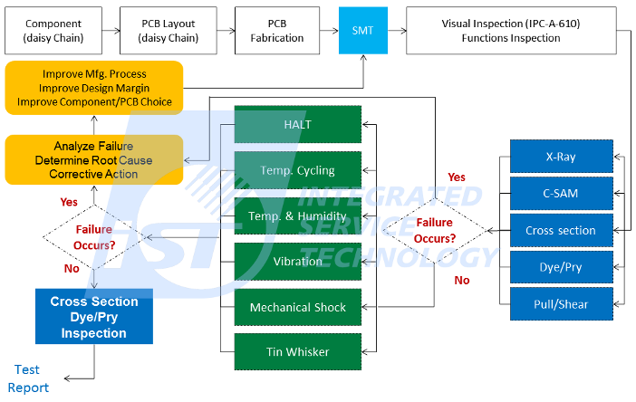
Figure 3: Pb-free validation flowchart
Furthering the Pb-free process for on-board information systems, the iST Lab where this author is now working has been consigned the validation of ABS and SRS safety function-critical ECU by international Tier 1 brand owners. This without a doubt marks that the automotive industry, which mandates the highest level of reliability, is adding the Pb-free process into its core personal safety electronic components.
The experiences of the iST Lab in working by Tier 1 tells that different areas may impose different requirements:
- Western automotive makers and Tier 1 owners pay more attention to product service life, set up test programs in terms of product life cycle, and accelerated tests including Arrhenius Model for thermal aging, Hallberg-Peck Model for high temperature and humidity and Coffin-Manson Model for temperature cycling.
- American manufacturers especially demand High Accelerated Life Testing (HALT) and aim to identify design flaws with Test to Failure. The goal is to improve design flaws at the design validation phase as shown in figure 4.
- Asian countries (Japan and South Korea) require ion migration and whisker validation. My educated guess suggests most of these electrochemical validations in Asia are made by long hours rather than accelerated testing. Products of Asian and Tier 1 makers subject to these tests may lend the impression that the actual products will have a longer automotive electronic product life cycle compared to those by western brands who put more effort into environment protection.
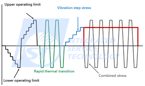
Figure 4: American automotive makers' HALT tests
- Step 5: System Level – Standard Specification from System Module to Tier 1 / Brand Owners
System module validation requirements may come at three stages:
- Rivalry: the company is faced with a live-or-die challenge and the immediate and only goal is to survive by launching products on the fastest timeline and at the lowest costs. There is nothing left to say about responsibility and quality.
- Alternative brand: the company is well established and is aiming to build up brand value. Quality verification is most likely subject to global automotive specifications, which almost always comes to the most widely adopted in the industry, ISO 16750 (Traditional Chinese edition CNS 15481, Simplified Chinese edition GB/T 28046 and Japanese edition JASO D014). There are four validations covered by it: electrical load, mechanical load, climate load, and chemical solvent load.
- Components for brand owner: there are no other options except being certified by the specification of the car maker or of Tier 1.
Our practical experience with the automotive supply chain at the iST Lab tells us that to sustain in the automotive industry, makers of consumer electronics products shall drop their long success history and devotion to quality and reliability without any compromise due to price factors. Automotive makers may demand a product adoption time span of up to 3-5 years of validation and an even longer period, 20 years, of after sale maintenance inventory. Owners have to have more patience and determination before stepping into the automotive industry.

Click to Watch the Video
For more details, please contact Daniel Chuang
Phone: +886-3-579-9909 Ext. 6403
Email:
TID@istgroup.com and
marketing_tw@istgroup.com